Performance Analysis
PERFORMANCE ANALYSIS
Winfoil has the ability to determine the performance of an aircraft design.
The performance characteristics that are calculated are
Stall Speed
Maximum Speed
Maximum Lift to Drag ratio and speed
Minimum Sink Speed
Wing Loading
Power Loading
The performance can be determined before or after the aircraft components are designed.
If the performance is determined after the components are designed then the wing, tail areas and drag coefficients can be loaded from the designs otherwise these have to be manually entered.
The Design Properties screen in the Design Cad screen will display the values entered in the Drag Breakdown for the matching component. This is useful when designing a wing, tail or fuselage component to match the required design performance.
The calculation units can be changed at any time by selecting different units in the Drag Breakdown screen.
Calculation units can be a combination of metric and imperial so you can have metric units on the Details tab and imperial on the Drag Breakdonw tab. Winfoil will automatically cater for the different units.
The performance of the design can be printed from the File Print menu item or by clicking on the Print Toolbar button.
The performance calculation relies on input of the following parameters
Aircraft Configuration (Details Tab)
Aircraft Weight (Details Tab)
Maximum Engine Power (Details Tab)
Maximum Wing Lift Coefficient (Drag Breakdown Tab)
Propeller Efficiency (Drag Breakdown Tab)
Flat Plate Area (Drag Breakdown Tab)
The Maximum Wing Lift Coefficient is the estimated maximum for the wing and is used to calculate the stall speed. Typically for an un-flapped wing this would be around 1.3. It will be higher if the wing has leading edge and/or trailing edge flaps or slots. Winfoil will default this value to 1.3.
The Propeller Efficiency is the estimated maximum propeller efficiency for the maximum speed calculation. This value is typically around 0.75. Winfoil will default this value to 0.8.
The Aircraft Configuration is used to determine which items appear in the Drag Breakdown tab. Therefore it is important to select the correct configuration.
Determining the performance of a scale Gee-Bee Z Electric R/C Pylon Racer
This tutorial will describe the steps required to estimate the performance.
The performance is determined after creating the design components (Wing, Horizontal and Vertical Tail surfaces). The dimensions of the model and power requirements were determined prior to creating the components and are based on an existing R/C design.
Create a Wing Design
Open the Design List screen. (File -> Design List menu item or CTRL D keys or click on the Design List toolbar button ![]() )
)
Click on the No button when prompted to use the Wing Design Wizard.
The wing design will be traced from a 3 view drawing of the Gee Bee Z Wing.
Enter the Design name as Gee Bee Z.
All design components must use the same name so that they are grouped together.
Select Wing type form the Type dropdown list.
Select inches as the measurement units.
Select the root and tip airfoils (Clark Y)
Press the Add button.
Click on the CAD tab to draw the wing design.
After clicking on the CAD tab you will be prompted to enter the wing span.
Enter 60 in the Span box.
Click on the Add Points toolbar button ![]() or right click and select Add Wing Points from the popup menu.
or right click and select Add Wing Points from the popup menu.
Click on the CAD screen to add the points which will define the outline of the wing.
Points are always added as pairs beginning with the leading edge and ending with the trailing edge.
Once the first point is added two guide lines will be displayed. The first will indicate the root chord position and the last the tip chord position.
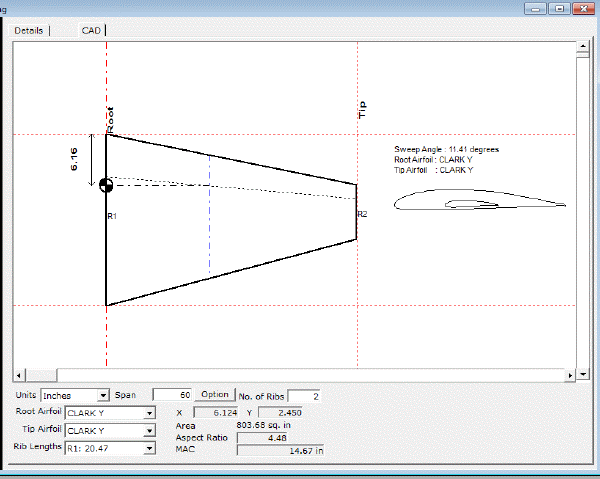
Add the second pair of points at the tip chord position. It does not matter if this coordinate pair is not exactly at the tip.
The CAD screen should look like this picture below.
Next we will adjust the tip coordinate.
Click on the Enter Points from Keyboard toolbar button ![]() or right click and select Enter Wing Coords from KeyBoard menu item.
or right click and select Enter Wing Coords from KeyBoard menu item.
Click on the Select Points keyboard button ![]() or right click and select the Select Points menu item.
or right click and select the Select Points menu item.
Next click on the CAD tab pane to select the tip wing coordinates.
The screen should look like the picture below.
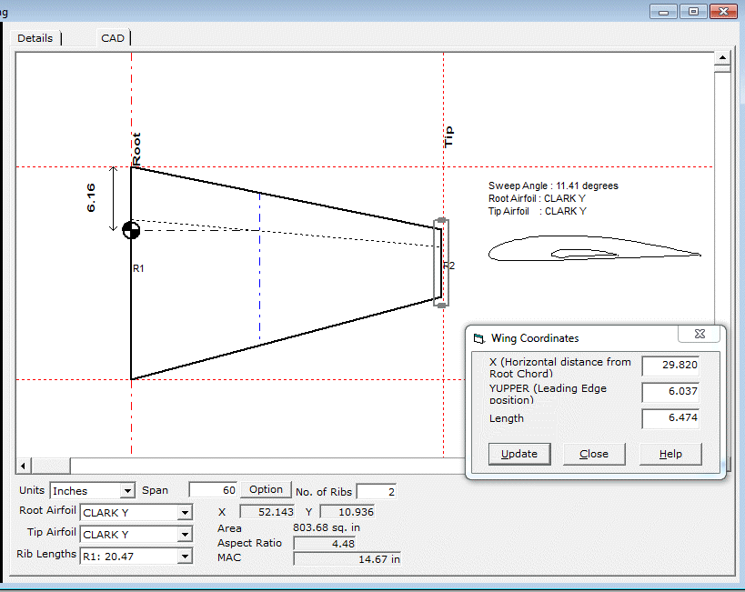
Enter 30 for the X value and press the Update button.
This action will move the tip coordinate pair to the tip of the wing design.
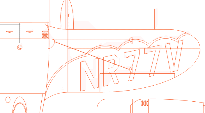
Next step is to get a picture of the wing to trace.
A screen shot of a DXF drawing of the Gee Bee is captured using the ALT-PRTSCRN buttons and this image is pasted into Windows Paint. This image is cropped to a size that would fit within the pane of the CAD tab. The size of this image does not have to be precise. The CAD pane can be scrolled if required.
The trace image looks like this
The picture is loaded into the CAD tab pane by pressing the Load Picture toolbar button ![]()
The CAD pane will look like the following.
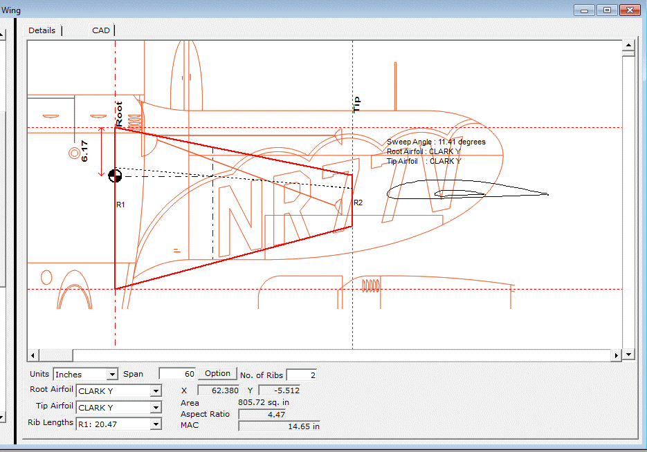
Next step is to align the wing design with the picture.
Press the Select Points toolbar button ![]() then select the root rib.
then select the root rib.
The CAD pane will look like the following.
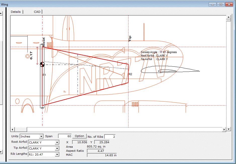
Click the mouse once within the grey bounding rectangle and drag this so that it lines up with the centerline of the wing picture. After releasing the button the wing will move to the new position lining up with the centerline of the picture.
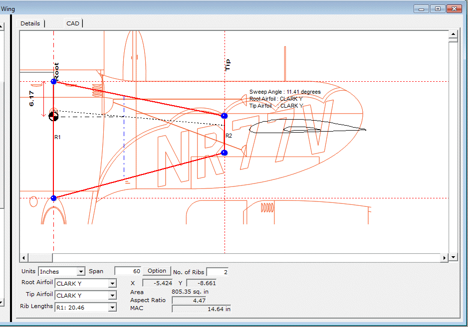
The next task is to rescale the wing so that the tip will match the wing picture.
This is done by setting the span to the appropriate size. Moving the mouse over the CAD pane so that it is over the furthest extremity of the tip gives an X value of 81.496 inches. This is the distance from the centerline to the wing tip.
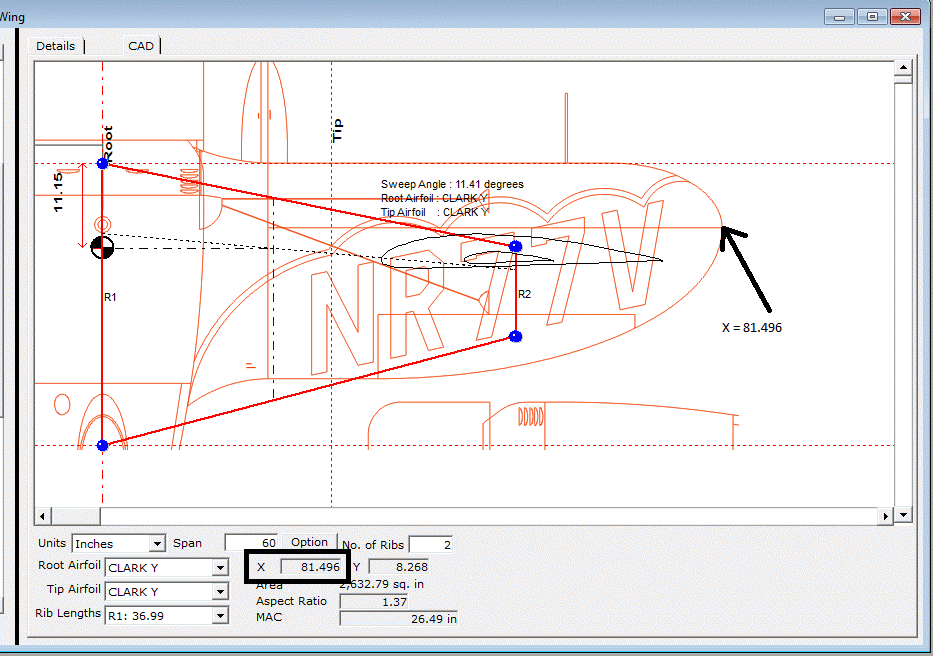
The span needs to be increased to 2 times the X value which is 162.99.
This value is entered as the span. The default setting for the span changes is to rescale the wing and maintain the aspect ratio. Click on the Redraw Wing toolbar button ![]() to refresh the wing drawing.
to refresh the wing drawing.
After doing this the CAD pane will look like the picture below.
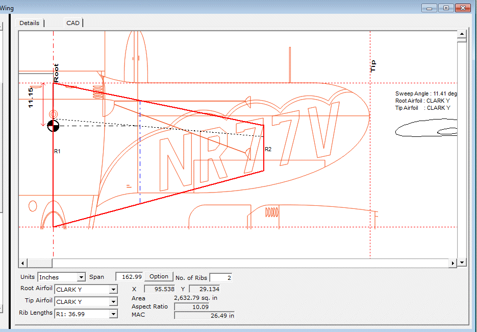
The wing tip reference line now lines up with the wing picture wing tip.
Now we can add wing coordinates and adjust the existing coordinates so that the wing shape matches the picture.
Click on the Add Wing Points toolbar button ![]() to add new points.
to add new points.
Coordinates are added as pairs starting with the leading edge and finishing with the trailing edge.
To edit a coordinate pair press the Select toolbar button ![]() . Click on the coordinates you wish to alter then click on the grey handles to move the leading or trailing edge coordinate.
. Click on the coordinates you wish to alter then click on the grey handles to move the leading or trailing edge coordinate.
Alternatively open the Enter Points from the Keyboard toolbar button. Select the points and change them in this screen.
After adding the remaining points the CAD pane will look like the picture below.
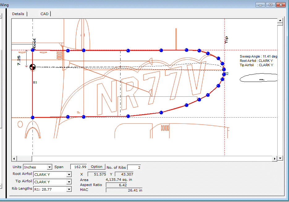
The next step is to rescale the wing so that it has the wing span that was originally required of 60 inches.
To do this the span is changed back to 60 inches and the Save toolbar button ![]() is pressed.
is pressed.
The wing design can then be magnified by pressing the Zoom In button ![]() so that it is an appropriate size on the screen.
so that it is an appropriate size on the screen.
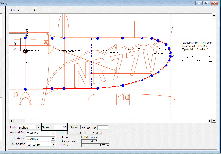
Winfoil will have calculated the wing area, aspect ratio and Mean Aerodynamic Chord location.
Create a Vertical Tail Design
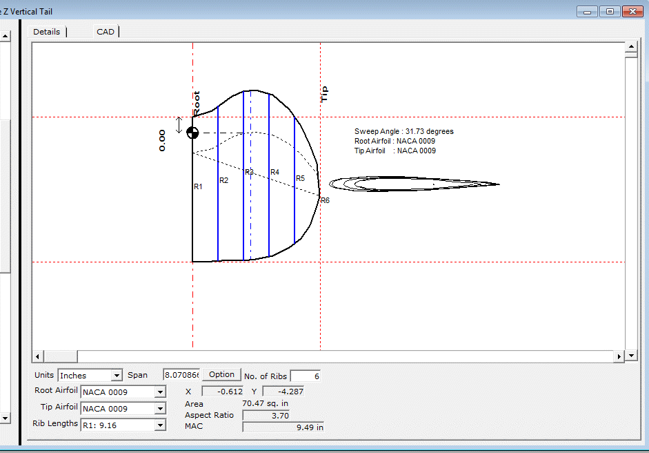
The steps taken to design the wing are repeated for the vertical tail resulting in the design shown below.
Create a Horizontal Tail Design
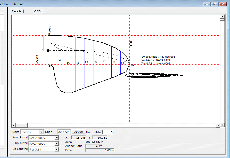
Similarly for the horizontal tail resulting in the design shown below.
Create a Specification for the Gee Bee Z
This design is available from the Winfoil web site from the following link
Click on one of the items in the Design List screen and click on the New button in the Details Tab.
Click on the No button when prompted to use the Wing Design Wizard.
Enter the name (same name as the components eg; Gee Bee Z).
Select Specification as the type from the Type dropdown list.
Select the measurement units.
Click Ok.
A blank Details tab will be displayed.
Select the type of aircraft (Pylon Racer)
Select the configuration (Monoplane)
Enter the estimated gross weight of the design (3.5 Kg)
Enter the maximum power that the engine will provide (1.5 Kw )
Complete the Drag Breakdown
Click on the Drag Breakdown tab.
Items are edited/changed by double clicking or selecting an item and pressing the Change button.
Pressing the Default button will reset the list and clear any settings that you have entered.
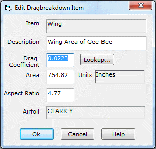
Wing Item
Double click on this item.
Press the Lookup button.
Winfoil will automatically load the drag coefficient and wing area values from the wing design for the Gee Bee Z.
You can manually override these values and can select a different airfoil if required.
Press the Ok button to save the details.
Fuselage Item
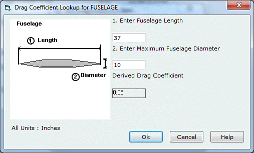
Double click on this item.
Press the Lookup button.
Winfoil will display a popup screen for determining the drag coefficient for a fuselage.
The length of the fuselage is 37 inches and the maximum diameter is 10 inches.
Entering these values results in a drag coefficient of 0.05.
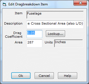
The area is manually calculated based on the maximum fuselage cross section which is circular.
As with the other drag breakdown items the drag coefficient and area can be overridden.
Press the Ok button to save the details.
Undercarraige Legs
Double click on this item.
Press the Lookup button.
Winfoil will display a message box with the a question regarding the fairing around the undercarriage leg. The Gee Bee Z undercarriage has a streamline fairing and wheel pants.
The Yes button is pressed and the drag coefficient of 0.3 is selected.
The frontal area of the undercarriage legs is estimated as 12.59 sq. inches and entered.
Press the Ok button to save the details.
Wheels
Double click on this item.
Press the Lookup button.
Winfoil will automatically determine a drag coefficient for a wheel of 0.7
The exposed frontal area of the wheels is estimated as 1 sq. inch and entered.
Press the Ok button to save the details.
Control Horns
Double click on this item.
Press the Lookup button.
Winfoil will automatically determine a drag coefficient for a control horn of 1.0
The exposed frontal area of the control horns is estimated as 0.2 sq. inches and entered.
Press the Ok button to save the details.
Horizontal Tail
Double click on this item.
Press the Lookup button.
Winfoil will automatically load the drag coefficient and wing area values from the horizontal tail design for the Gee Bee Z.
Press the Ok button to save the details.
Vertical Tail
Double click on this item.
Press the Lookup button.
Winfoil will automatically load the drag coefficient and wing area values from the vertical tail design for the Gee Bee Z.
Press the Ok button to save the details.
As each item is entered the performance is automatically calculated.
None of the drag items are mandatory however the more detail that is entered, the more accurate the performance analysis.
Leaving the mouse pointer over the Drag Breakdown list will display a popup window displaying the calculated performance of the design.
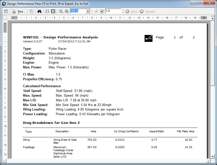
Report
A report can be printed from the File Print menu item or by clicking on the Print toolbar button.
Export Performance Analysis
The performance data can be exported two different ways.
- Export directly to Excel.
You must have Microsoft Excel installed on your computer to use this feature.
Click on the Export toolbar button ![]() or select the File Export menu item.
or select the File Export menu item.
Select the Design Performance Data to Excel Spreadsheet option.
Select the name of the design from the dropdown name list.
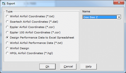
Click on the Ok button.
You will then be prompted to select the Excel program file Excel.exe.
This will normally be installed in the c:\Program Files\Microsoft\Office folder on your computer.
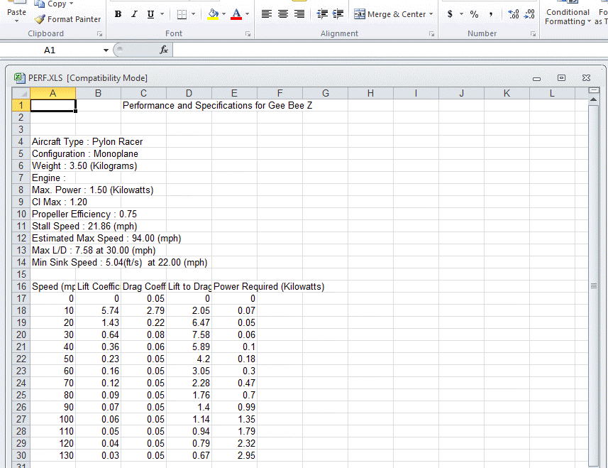
You will need to select this file. After doing this Excel will be started and the data will be transferred to a new Excel Worksheet as shown below
- Export performance report to PDF, Excel, Text, RTF, HTML or TIFF.
Open the Design List screen. Select the design specification in the tree list on the left most side of the screen. Click on the Drag Breakdown tab. Click on the Print toolbar button ![]() or
or
Select the File Print menu item.
This action will generate the Performance Report.
Press the F6 function key. You will then be able to select the required export format.
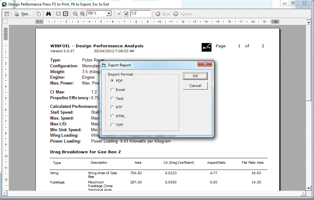
The Excel export option does not need Excel to be installed on the computer in order to generate the output.
If you are going to apply additional formatting or wish to edit the exported data it is recommended that you export the data using option 2 and select the HTML export.
You can then open the HTML file in Excel 2007 or 2010 and apply the formatting. You can then save it in Excel format or copy and paste it into Microsoft Word or other Word processing software.