Spar Design Example
This screen is accessed by selecting the Design List menu item or by clicking on the
 Design List toolbar button, followed by selecting the CAD Tab and
clicking on the  Spar Design toolbar button.
Simple Three Spar Wing
This example illustrates the steps required to design a simple three spar wing. These techniques can be extended to create more complex structures.
The wing will consist of three spars;
1. Leading Edge spar.
2. One intermediate spar (Main spar).
3. Trailing Edge spar.
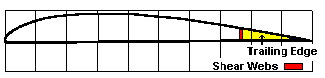
The intermediate spar will also have shear webs facing each side of the spar. These transfer shear loads through the spar. The intermediate spar will consist of an upper and lower spar section. The following diagram shows the detail of this design;
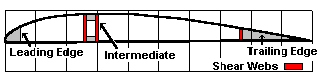
The design steps are as follows;
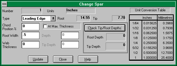
1. Add leading edge spar.
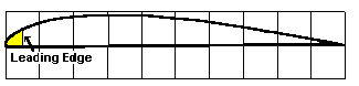
Select Leading Edge from the spar type dropdown list. This spar is placed at the start of the wing therefore the position is 0%. This spar is full depth and is defaulted to 0. The width set to 0.5 inch No spar web is specified for this spar. If a spar web is required , enter a value for the web thickness. The web will then be placed on the inner face of the spar. To save any changes click on the UPDATE button. To exit without changing , click on the CLOSE button. To view help click on the HELP button.
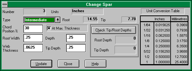
2. Add intermediate spar.
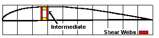
Select Intermediate from the spar type dropdown list. This spar is placed at the point of maximum thickness. This provides the greatest strength for the least weight. To find this location, Click on the At Max. Thickness checkbox . The spar has a depth and width set to 0.25 inch (standard spruce spar stock ie; 6 mm). Because this depth is less than the depth of the airfoil , an upper and lower spar section will be created. Spar webs have been specified as 1/16 inch or 1.5 mm. If this dimension is left as zero , no spar webs will be plotted. To save any changes click on the UPDATE button. To exit without changing , click on the CLOSE button. To view help click on the HELP button.
3. Add trailing edge spar.
Select Trailing Edge from the spar type dropdown list. This spar is placed at the desired position. This spar depth defaults to zero as it is a trailing edge spar. The spar width is calculated automatically based on the chordwise starting position. A single spar web is specified as 1/4 inch. This will serve as an aileron spar for the strip ailerons. By default , if a spar web thickness is specified then a single web will be plotted. If this dimension is left as zero , no spar webs will be plotted.
To save any changes click on the UPDATE button. To exit without changing , click on the CLOSE button. To view help click on the HELP button.
