Wing CAD Example 1
Constant Chord Wing
Please note this example assumes that theWing WizardWING_WIZARD has not been used, ie it is a new wing or tail design.
This simple example illustrates the techniques required to design a wing or tail in Wing CADWING_CAD using a mouse.
In this example a constant chord wing will be designed.
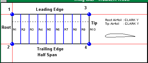
As this wing is a constant chord rectangular planform only four points are needed to be defined. These are as follows;
1. Root Leading Edge
2. Root Trailing Edge
3. Tip Leading Edge
4. Tip Trailing Edge
It is in this order that the design will be constructed. The wing is designed by adding a chord coordinate pair. Therefore for this design two sets of points are required. One for the root chord and one for the tip chord. For a new design the first set of points is always the root chord.
Steps are follows;
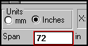
1. Enter the wing/tail span. This is the full span of the wing or tail.
2. Select the measurement units by clicking on the appropriate unit of measurement
3. Click on the Add Points Button.

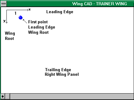
4. Point 1.
Move the mouse over the wing design window. Click on the mouse to place the leading edge position of the root chord. It is best to place this near the left upper region of the design window.
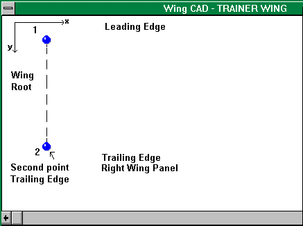
5. Point 2.
Move the mouse down and click at the desired position for the trailing edge of the root chord.
The distance y is the distance from the leading edge to the trailing edge. To obtain a 300 mm root chord, move the mouse down until the y dimension = 300.
Each chord of the wing is set as a pair the first or upper point is the leading edge. The lower point is the trailing edge. The vertical direction is the direction to the front of the aircraft. The horizontal direction is the spanwise direction. The wing or tail is always plotted as a half wing or tail (right half).
6. Point 3.
Move the mouse in the horizontal direction (to the right) until the x distance is half the span of the wing or tail. Click on the mouse when the vertical position is level with the root chord leading edge.
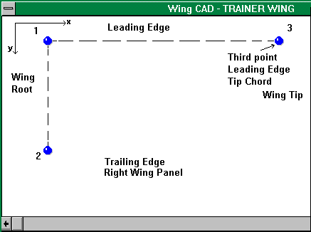
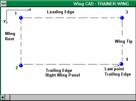
7. Point 4.
Move the mouse in the vertical direction downwards to place the trailing edge tip chord position.
Click on the mouse when the vertical position is level with the root chord trailing edge.
8. Click on the wing Save button to save the changes

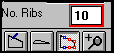
9. Enter the desired number of ribs per wing/tail half. The minimum number is 2 (root and tip ribs).
Spacing is limited to equal spacing.
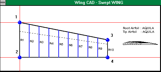
10.Click on the Redraw button to redraw the wing. The wing layout should look something like this.

11. Click on the Calculate button to calculate the wing area, aspect ratio and mean aerodynamic chord.

Other wing shapes are simply a variation of the technique used in the above example.
Eg;
 Swept wing 4 points. Follow the numbering order to add points.
Tapered wing 6 points. Follow the numbering order to add points.
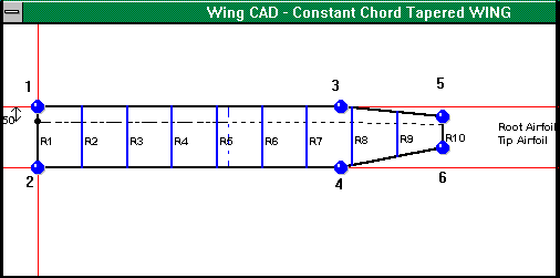
 Always add points as a set, Leading Edge first followed by Trailing Edge.