PRINT WING SCREEN
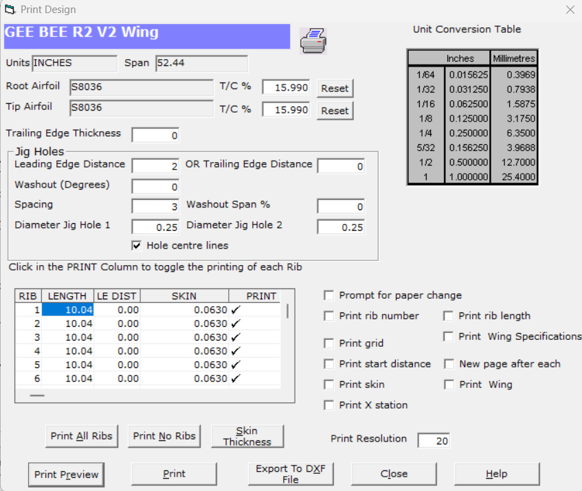
This screen controls the printing of ;
1. Wing Ribs
2. Wing Specifications
3. Wing Planform
You may select to print all or any combination of the above.
This screen also is used to export ribs and wing/tail designs to DXF files for import into CAD programs such as AutoCAD.
Name
This is the name of the currently selected wing.
Type
This is the type of wing. Eg; Vertical Tail, Horizontal Tail or Wing.
Units
Measurement units. Eg; Inches or Millimetres.
Root Airfoil
The airfoil section selected for the wing root.
Tip Airfoil
The airfoil selected for the wing tip.
T/C%
This is the airfoil maximum thickness. You may vary this by entering a new value for the thickness. Winfoil will automatically calculate the new coordinates for the airfoil based on the ratio of the new thickness and the original thickness. To reset the thickness to its original value , click on the Reset button. This setting can be varied for root and tip airfoils. If different values are entered then the thickness will be varied linearly along the span. Note, these settings override the airfoil thicknesses in the Design Properties Screen.
Trailing Edge Thickness
This is used to change the thickness of the trailing edge. This is expressed as a size.
Jig Holes
This is used to plot holes on the ribs to align the ribs in a wing jig.
Two holes are plotted in each rib. These can be viewed in the Print Preview screen.
Jig Holes are also plotted when ribs are printed to DXF files.
Leading edge position and spacing are checked when printing the ribs to ensure that the jig holes will not be located outside the ribs. A warning message will be displayed if this is the case and the hole will not be drawn.
These details are saved for the design when this screen is closed.
Please note washout settings are not yet functional.
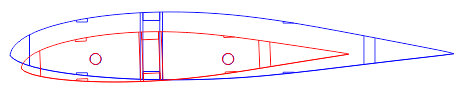
Washout and Washout Span can set to align the jig holes so that the wing will have the desired washout at the wing tip.
An example is shown below. The tip airfoil is red. The root airfoil is blue. The washout is 2.5 degrees.
The start of the Jig Holes can now be specified from the Leading Edge or Trailing Edge.
Entering a value in either will zero the other value.
Leading Edge Distance
This is the distance from the leading edge to the center of the first jig hole.
OR
Trailing Edge Distance
This is the distance from the trailing edge to the center of the first jig hole.
Washout (Degrees)
Jig Hole washout angle. Tip will have a lower angle of attack to prevent tip stalling.
A positive value is required.
Spacing
This is the distance between the two jig holes.
Washout Span %
This value specifies the distribution of the washout over the wing span.
100% means across the entire span of the wing.
A value must be entered otherwise no jig holes will be plotted.
Diameter Jig Hole 1
This is the diameter of the first jig hole.
Diameter Jig Hole 2
This is the diameter of the second jig hole.
Hole Centre Lines
Check this box to plot jig hole center lines to allow for drill alignment.
A list of the Ribs for the wing is listed on the screen. If there are more ribs than will fit in the grid then you can scroll the grid by moving the vertical scroll bar on the right of the grid.
The Print column of the grid indicates if the rib is to be printed. This is toggled on and off by clicking in the appropriate cell. A tick means print, a cross means do not print.
There are three buttons immediately below the grid.
Print All Ribs
Click on this button to tick all ribs to be printed.
Print No Ribs
Click on this button to mark all ribs to not be printed.
Skin Thickness
Click on this button to edit the skin thickness of a rib. Select a rib by first clicking on a rib in the list. Alternatively double click on a rib. The Edit Skin Thickness screen is shown below.
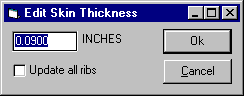
To apply the skin thickness to all ribs, click on the Update all Ribs checkbox. Click on the Ok button to accept the change or click on the Cancel button to exit without making any changes.
The changes will be applied to the database so that the changes are permanent.
The Skin Thickness can also be set in the Rib ViewRib_View screen.
There are a number of print options available. These are as follows;
Rib Number
Print the number of the Rib. Ribs are numbered sequentially starting from the root of the wing and ending at the tip of the wing.
Rib Length
The length of the Rib is printed with the selected units of measurement.
Wing Specifications
The wing specifications are printed. These include;
1. Wing area
2. Wing aspect ratio.
3. Mean aerodynamic chord length and position.
4. Measurement units.
5. Type.
6. Wing root airfoil section.
7. Wing tip airfoil section.
8. Number of ribs per wing half.
9. Rib spacing.
10. Each rib number, length and distance from the leading edge reference lineLEADING_EDGE_REFERENCE_LINE
X Station
This is the distance horizontal distance spanwise from the wing root.
Grid
Selecting this option prints a grid over each rib with stations marked at ten percent intervals.
New Page after Each
Selecting this option will result in each rib being printed on separate pages.
Start Distance
Select this option to print the distance from the leading edge reference lineLEADING_EDGE_REFERENCE_LINE
Print skin
Select this option to print the skin line for wing or tail ribs.
This feature is handy for DXF export and CNC cutting.
Wing Planform
Select this option to print the wing planform with the mean aerodynamic chord position and the rib positions. Selecting this option will cause the WING PANEL PRINT SELECTION SCREENWing_Panel_Print_Selection to appear.
Print Resolution
Varying this will alter the degree of accuracy of the airfoil plot.
10 - rough plot , 100 - fine plot.
Increasing this number will also increase the time required to plot the airfoil.
Print Preview
This feature allows the specification, wing or tail design and ribs to be previewed before printing.
Print to DXF File Button
DXF FILEPRINT_TO_DXF_FILE
Cancelling the Print Job
A dialogue box will appear after the PRINT BUTTON is clicked on indicating the progress of printing.
You may cancel the print job at any time by clicking on the CANCEL button or if this dialog box has disappeared by deleting the print job in PRINT MANAGER.
Use the PRINT SETUP COMMANDPRINTER_SETUP_COMMAND in the File menu to change the print orientation to Landscape or Portrait .