How to design a wing in the Wing Cad screen
HOW TO DESIGN A WING IN DESIGN CAD
Steps to create a new design with the Design Wizard
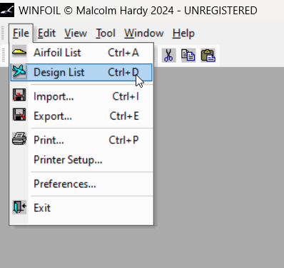
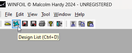
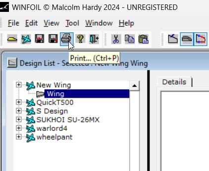
1. Open the Design List screen by selecting the Design List menu item from the File Menu or
click on the Design List toolbar button.
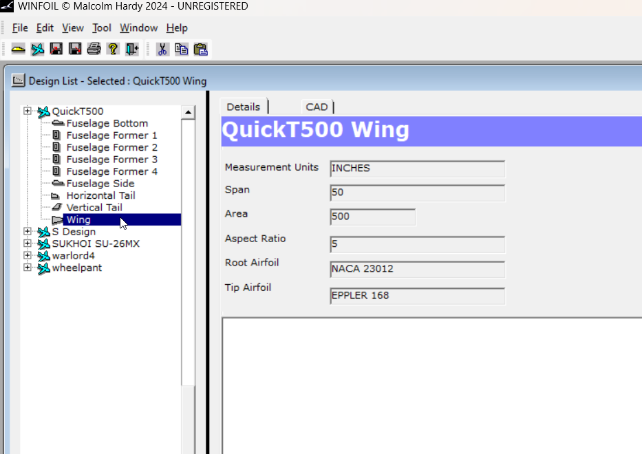
2. Click on any the designs in the list on the left of the screen.
3. Click on the Details tab.
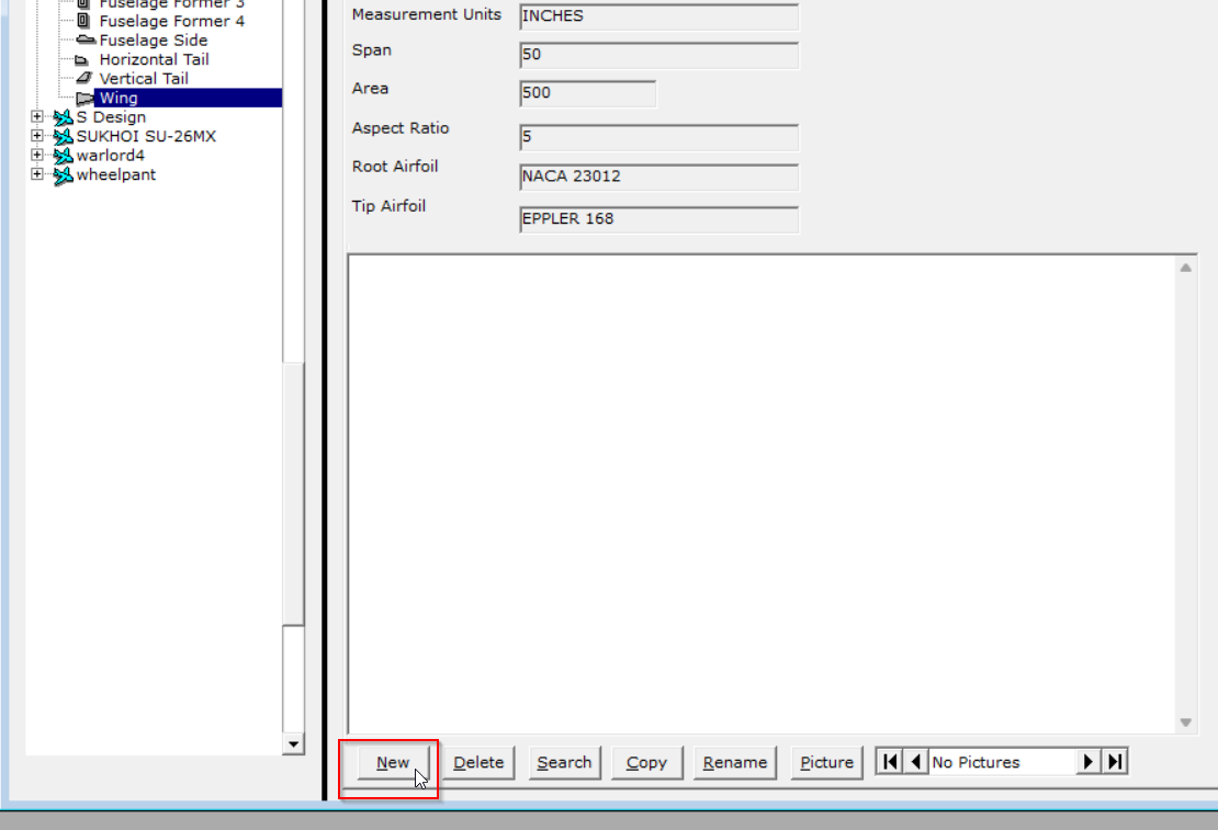
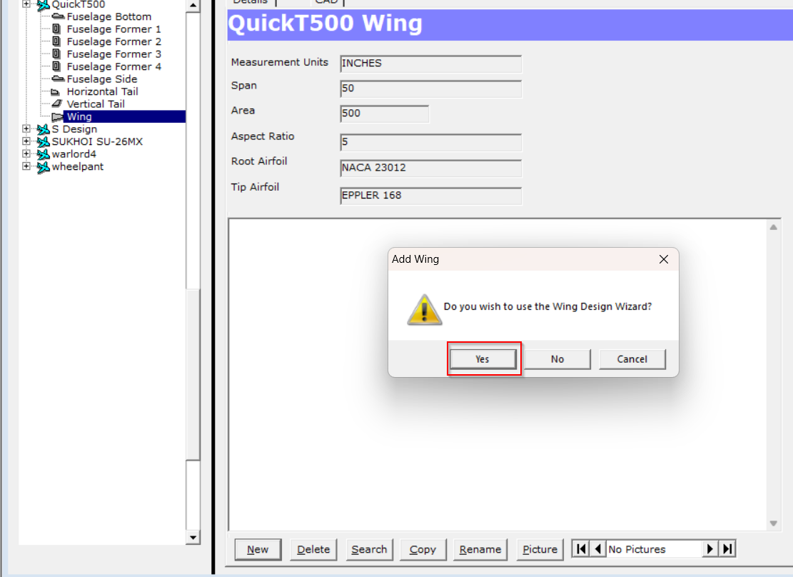
4. Click on the New button (at the lower part of the tab screen) to create a new wing design.
5. Click on the Yes button to use the Wind Design Wizard.
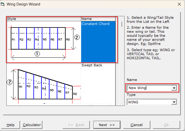
6. Select a wing planform (style) from the list, then enter the name of the wing design.
Click on the Next button.
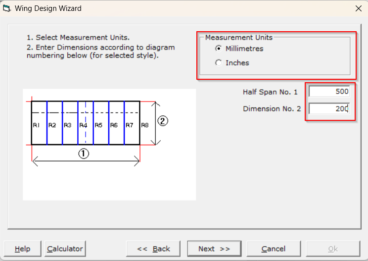
7. Select measurement units, then enter the appropriate dimensions.
Click on the Next button
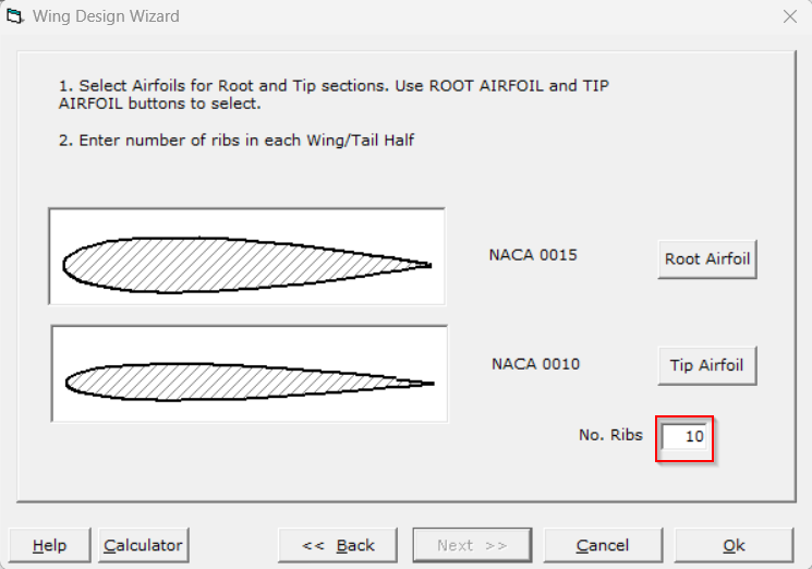
8. The next step is to select root and tip airfoild. Click on the Root Airfoil button and select an airfoil from the list.
Repeat this process for the Tip Airfoil.
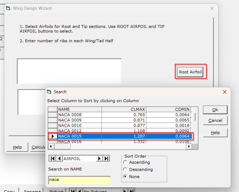
9. Enter the number of ribs per wing half, then press the Ok button.
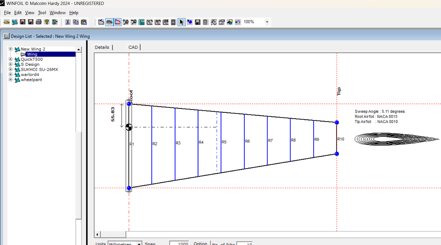
10. Click on the CAD tab to view the design.
The CAD view displays the right half of the wing design.
The blue lines show the position of the ribs.
The number of ribs, spacing and wing shape can be altered if required.
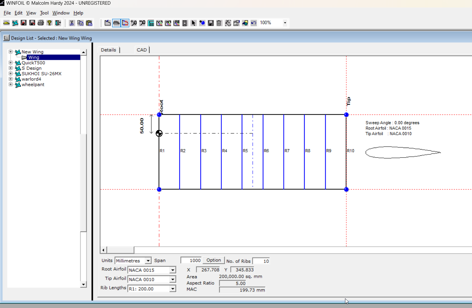
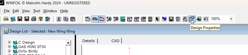
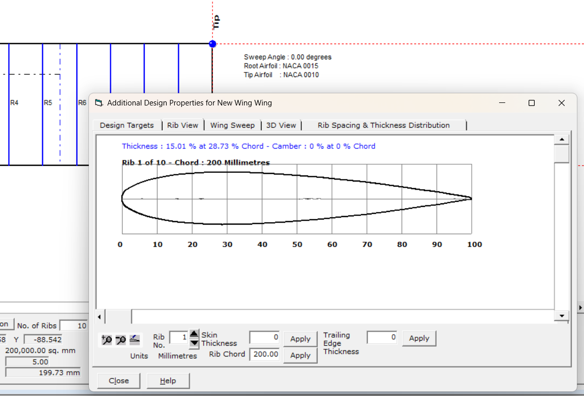
You can view the individual ribs by clicking on the Design Properties toolbar button.
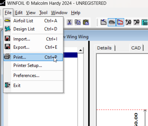
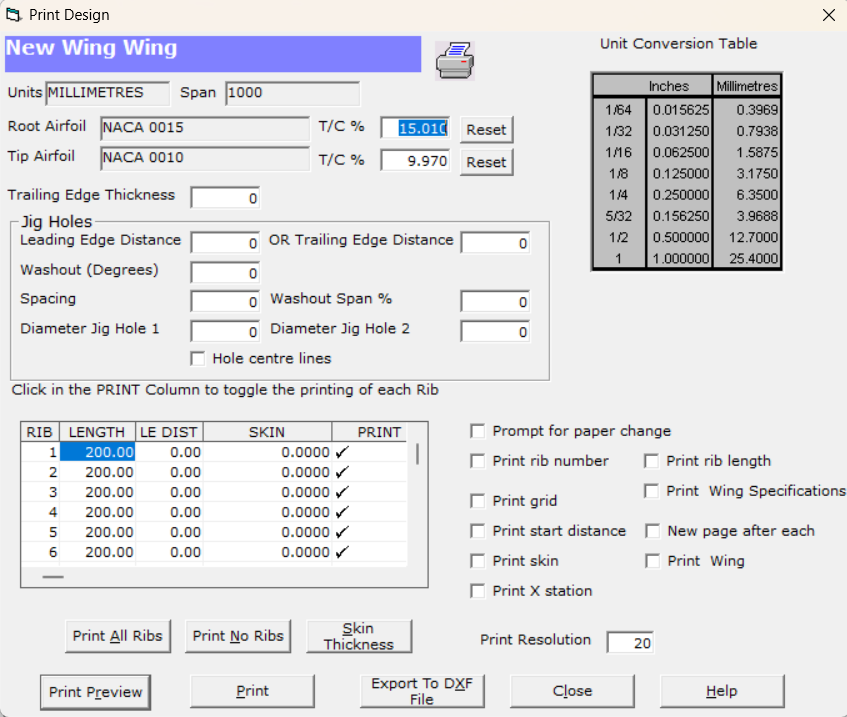
To print or export the wing design and ribs, click on the File Print menu or click on the Print button in the toolbar.
Steps to create a new wing design without using the Design Wizard
1. Open the Design List screen by selecting the Design List menu item from the File Menu or
click on the Design List toolbar button.
2. Click on any the designs in the list on the left of the screen.
3. Click on the Details tab.
4. Click on the New button (at the lower part of the tab screen) to create a new wing design.
5. Click on the No button to not use the Wind Design Wizard.
This action will result in the Add Design item screen bein displayed.
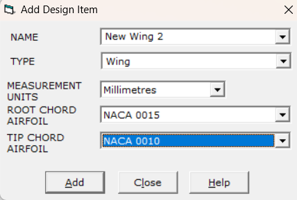
Enter the name of the new Wing.
Select the design type wing.
Select the wing measuerment units.
Select the root and tip airfoils.
Click on the Add button.
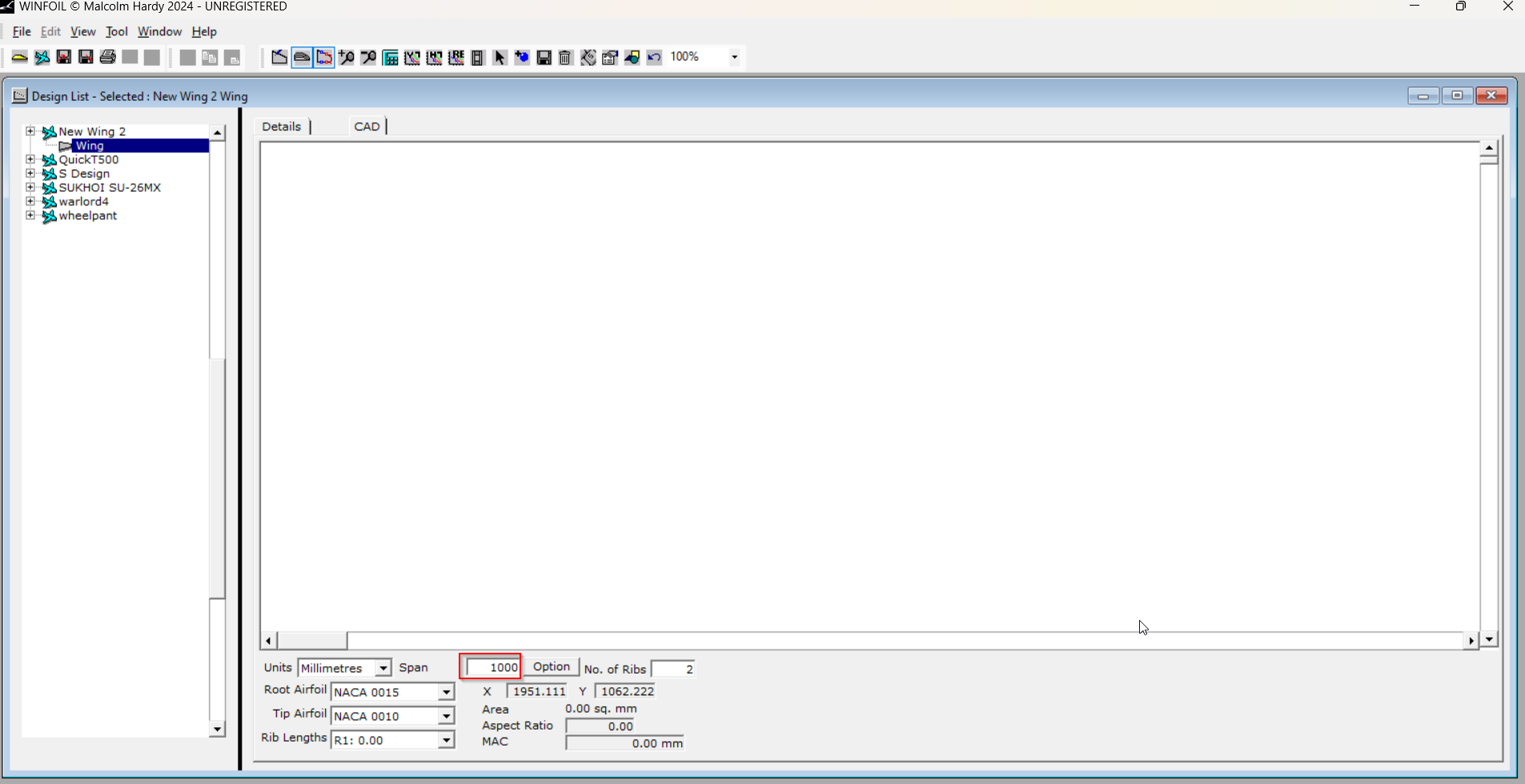
8. The WING CAD SCREEN will appear.
9. Input the full SPAN of the wing or tail in the SPAN box.
10. Click on the ![]() button to turn off rib redrawing.
button to turn off rib redrawing.
11. Click on the ![]() button to start adding wing coordinates using the mouse.
button to start adding wing coordinates using the mouse.
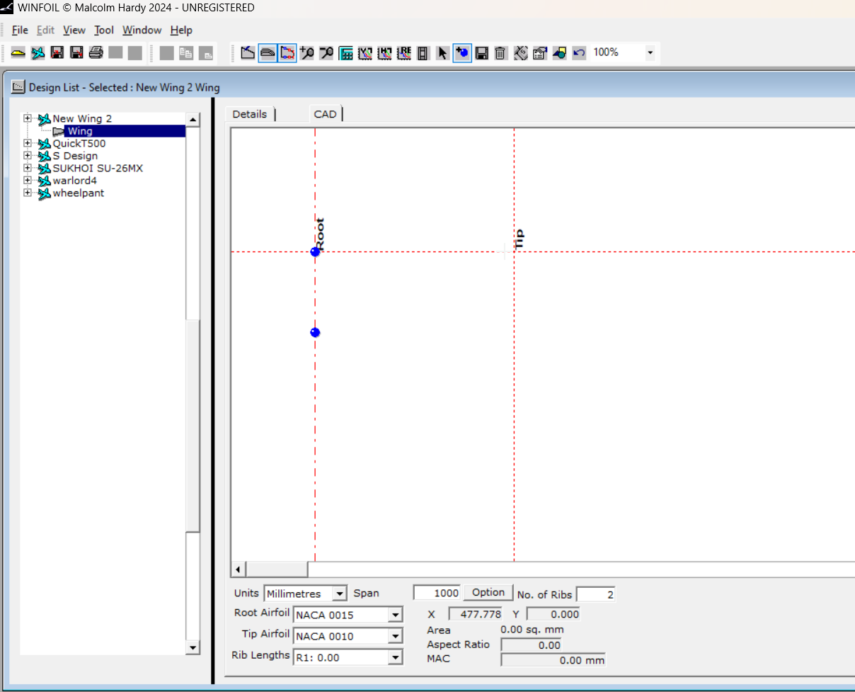
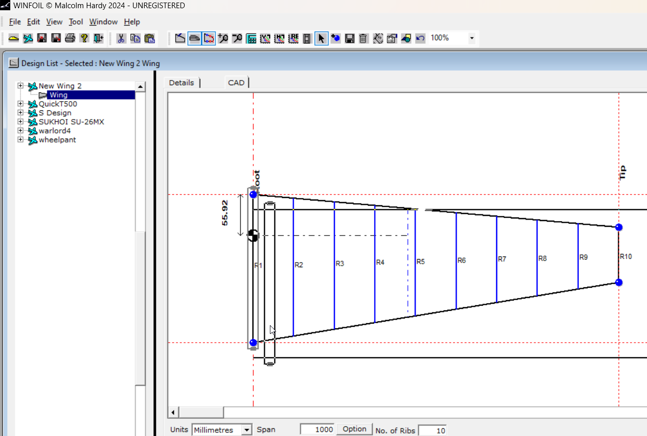
12. Move the mouse pointer over the wing window and click with the left mouse button when the
selected position has been achieved for a leading edge coordinate.
13. Move the mouse pointer down to add the trailing edge coordinate. Click with the left mouse button
again. Remember if you wish to undo or cancel these operations , click on the right mouse button.
14. Continue to repeat steps 9 & 10 until all the necessary points have been added to define the
wing or tail shape.
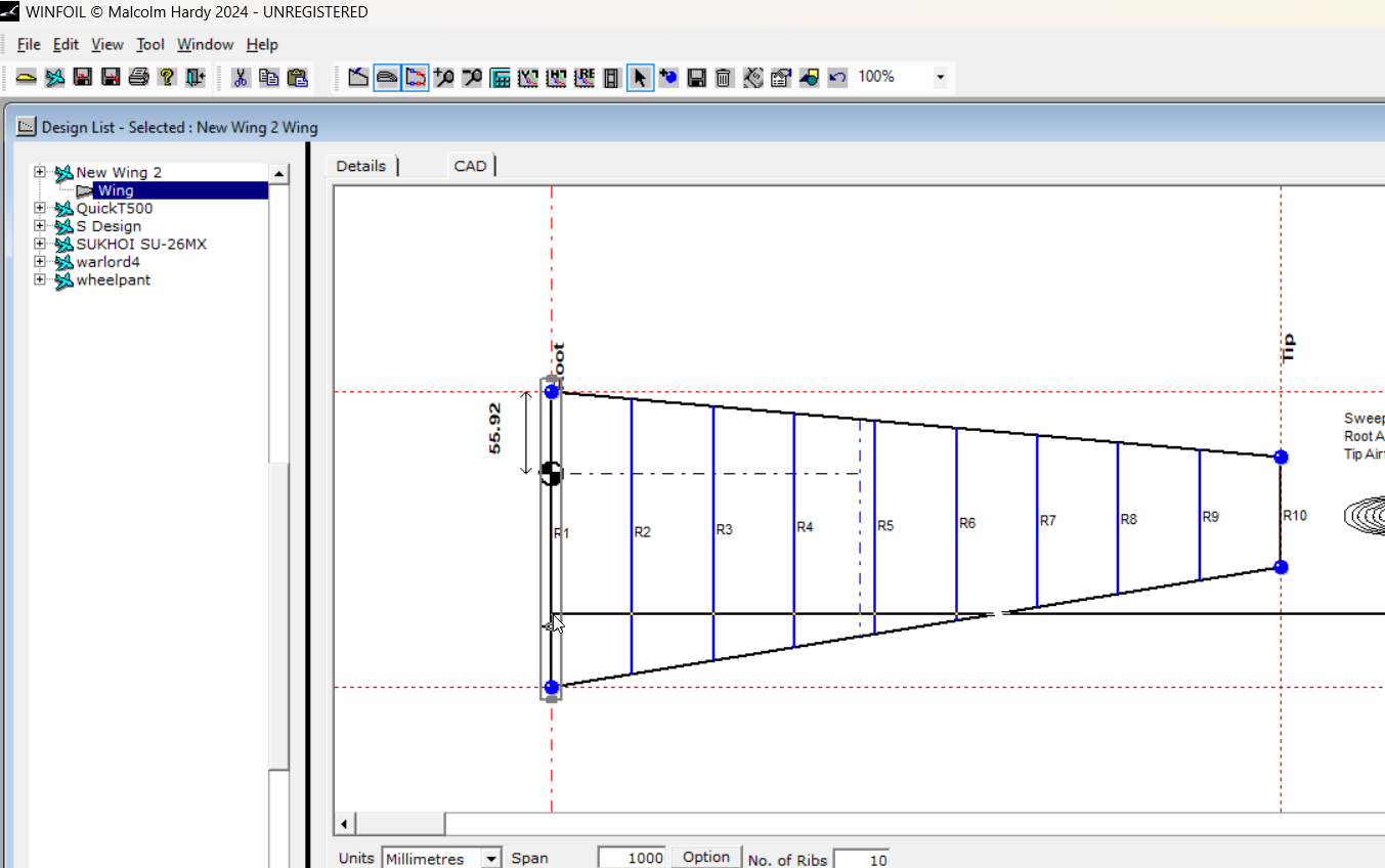
15. Click on the ![]() button to accept the changes and redraw the wing or tail.
button to accept the changes and redraw the wing or tail.
Screenshot after adding the last 2 coordinates and pressing the save button.
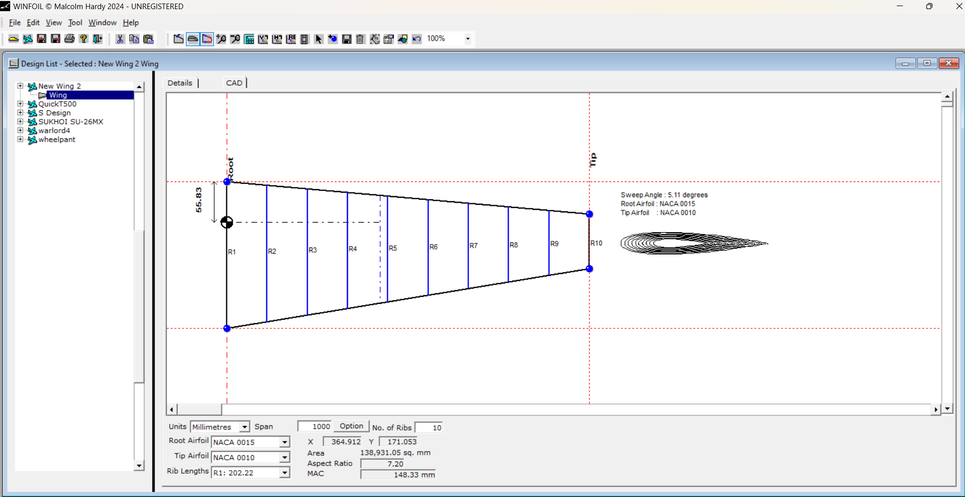
16. Enter the required number of ribs per wing half in the RIB NO. box. Click on the
![]() button to redraw the wing or tail.
button to redraw the wing or tail.
17. Click on the ![]() button to perform area, aspect ratio and mac calculations.
button to perform area, aspect ratio and mac calculations.
Remember; at any time you wish to scroll or enlarge or decrease the size of the plot , either move the horizontal and vertical scroll bars either side of the wing window or click on the ![]() button to enlarge
button to enlarge
the plot or the ![]() button to reduce the size of the plot.
button to reduce the size of the plot.
Steps to modify an existing design using a mouse;
Note, any changes to the shape of the wing will automatically change the rib lengths.
1. Position the plot and scale such that the points which need to be modified can clearly be seen.
2. Click on the ![]() button to identify a coordinate pair.
button to identify a coordinate pair.
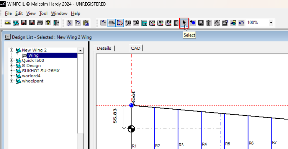
3. Move the mouse pointer over the wing window and click with the left mouse button near the coordinate pair you wish to modify.
4. A grey rectangle will appear framing the coordinate pair.
5. To move the coordinate pair , position the mouse pointer within the frame. Whilst holding the left mouse button down, drag the frame to the desired position, then let go of the left mouse button . This action will shift the position of the wing coordinate pair.
6. To move one of the coordinates belonging to the pair (you may only shift the coordinate up or down)
click on the grey HANDLE and drag it up or down to the desired position.
Either of the above actions will automatically save the changes.
To undo the change, click on the ![]() button.
button.
To move the entire wing or tail ;
1. Position the plot and scale such that the wing or tail root is visible. (Rib 1)
2. Click on the ![]() button to identify a coordinate pair.
button to identify a coordinate pair.
3. Move the mouse pointer over the wing window and click with the left mouse button near the wing or tail root (Rib 1).
4. A grey rectangle will appear framing the coordinate pair.
5. Position the mouse pointer within the frame. Whilst holding the left mouse button down, drag the frame to the desired position, then let go of the left mouse button . This action will shift the position of the entire wing or tail.
Steps to create a new design using keyboard data entry;
1. Select the NEW button in the Design List screen.
2. Enter or select the appropriate data in the ADD WING SCREEN.
3. Click on the ADD button in the ADD WING SCREEN.
4. The WING CAD SCREEN will appear.
5. Input the full SPAN of the wing or tail in the SPAN box.
6. Click on the ![]() button to turn off rib redrawing.
button to turn off rib redrawing.
7. Click on the ![]() button to show the wing coordinates screen.
button to show the wing coordinates screen.
8. Enter the coordinates for the coordinate pair based on the distance from the LEADING EDGE REFERENCE LINE.. Click on the UPDATE button to accept the coordinates.
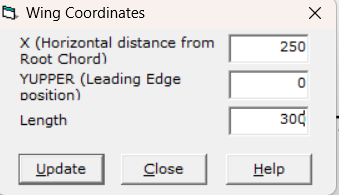
9. Continue step 8 until all the necessary coordinates are entered, then click on the
CLOSE button.
10. Enter the required number of ribs per wing half in the RIB NO. box. Click on the
![]() button to redraw the wing or tail.
button to redraw the wing or tail.
11. Click on the ![]() button to perform area, aspect ratio and mean aerodynamic chord calculations.
button to perform area, aspect ratio and mean aerodynamic chord calculations.
Steps to modify an existing design using keyboard data entry;
1. Position the plot and scale such that the points which need to be modified can clearly be seen.
2. Click on the ![]() button to identify a coordinate pair.
button to identify a coordinate pair.
3. Click on the ![]() button to show the wing coordinates screen.
button to show the wing coordinates screen.
4. Move the mouse pointer over the wing window and click with the left mouse button near the coordinate pair you wish to modify.
5. A grey rectangle will appear framing the coordinate pair and the coordinates will automatically
be displayed in the WING COORDINATES SCREEN
6 Change these coordinates as required and click on the UPDATE button.
7. When finished, click on the CLOSE button in the WING COORDINATES SCREEN.